Products
- Wind Tower Welding Line
- Welding Manipulator
- Fiber Laser Marking Machine
- CNC welding machine
- Hard Facing Machine
- Welding Positioner
- Welding Robot
- Horizontal Tank Welder
Contact Us
Wuxi Welding Machinery Co.Ltd
Address:Yangnan Road,Luoshe Town,Wuxi City,China
Mobile:+86-13815101750
Tel:+86-510-83555592
Fax:+86-510-83559158
E-mail:sales@weldc.com
Website:www.weldc.com
Your Position: Home>Products>CNC cutting machine>CNC Wire Cutting Machine
CNC Wire Cutting Machine
Description:
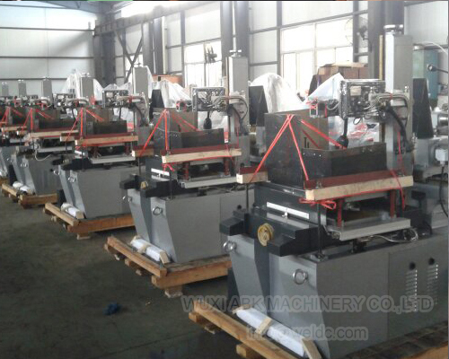
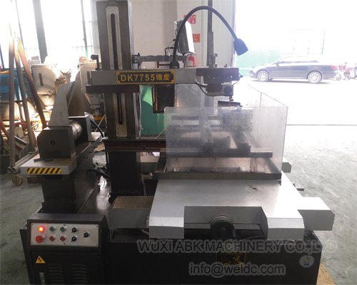
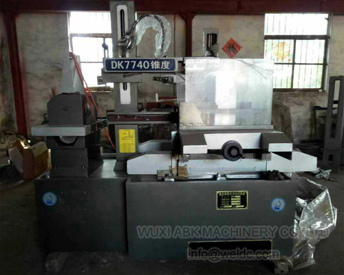
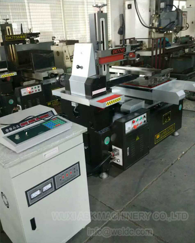
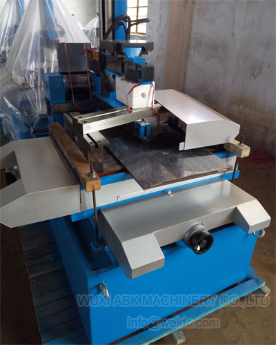
The machine tool is composed of the machine tool bed, coordinate worktable, wire drive device, wire support, operation liquid system, electric parts and accessories.The wire electrode used for machining is wound on the wire storage cylinder evenly and its high-speed to-and-fro movement is driven through the guide wheel on the wire support.The work piece is installed on the clamp of the worktable and is fixed with the press head screws.The worktable drives the work piece to move in the programmed track.There is sparkle discharge between the work piece and the wire electrode so as to create high heat to melt the corroded metal and to realize cutting purposes.The high-end machine adopts precise ball screw linear guide track.High column matches electric lift to adjust the gap of guide wheel and large swing taper machine matches electrode wire wire expansion mechanism.We also produce semi-closed environmental-protection machine.The diameter range of molybdenum wire is 0.12mm~Φ0.18mm (moly wire diameter over than Φ0.18mm should be customized).The maximum working speed is over 100mm ²/min and the best surface roughness is less than Ra2.5 μm.
Features
1.Large travel , High cutting speed.
2.Four axes independent UV work.
3.Work pieces to 600mm thick.
4.Taper angles up to ± 30°.
5.Standard model is equipped with ± 3° taper attachment.
6.Molybdenum wire diameter 0.12~0.22 mm (down to 0 .08mm).
7.Accuracy: 0.015mm, even 0.01mm.
8.Roughness: Ra 1.6-2.5 µm.
9.Low consumption, material saving.
10.Closed loop glass scales on all four axes for positional accuracy of 0.005mm.
11.Advanced CAD/CAM software with file transfer and translation capabilities.
12.High cutting speed modular is optional.
Control system ( HL, HF, W-Cut, A-Cut)
A)Microcomputer process control system
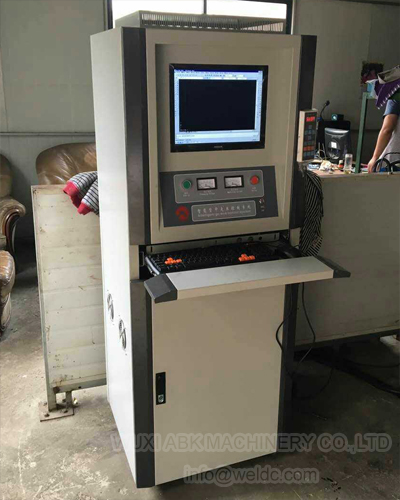
B)PC control system.
C)Luxury cabinet control.
Optional:
1.Taper cutting accessory. (± 15°, ± 30°)
2.Linear rail.
3.Protection cover.
4.Higher speed control board, improve the efficiency 30-40%.
5.Middle speed control system.
Parameter
Type | Worktable dimension(mm) | Worktable travel(mm) | Maximum workplece thickness(mm) | Maximum taper angle | Max.Load carrying capacity(KG) | Total weight(kg) | Machine package dimension(mm) | Remarks |
DK7720 | 250*420 | 200*250 | 250 | 0°-12°/80mm | 200 | 800 | 1060*800*1100 | Wire diameter:0.10mm-0.20mm; Speed of electrode wire:11m/s; Power supply:50Hz,380V; Power consumption of machine tool:less than 2KVA |
DK7725 | 330*520 | 250*320 | 400 | 250 | 900 | 1400*920*1350 | ||
DK7732 | 360*600 | 320*400 | 500 | 350 | 1000 | 1500*1200*1400 | ||
DK7732B | 410*670 | 350*450 | 500 | 400 | 1100 | 1600*1300*1400 | ||
DK7740 | 480*680 | 400*500 | 500 | 450 | 1300 | 1700*1400*1400 | ||
DK7740B | 520*745 | 450*550 | 500 | 600 | 1400 | 1750*1500*1400 | ||
DK7740F | 480*820 | 400*630 | 500 | 700 | 1500 | 2100*1500*1400 | ||
DK7745F | 520*820 | 500*630 | 600 | 700 | 1600 | 2100*1500*1400 | ||
DK7750 | 564*904 | 500*630 | 600 | 800 | 1900 | 2100*1700*1740 | ||
DK7750F | 594*1064 | 500*800 | 600 | 1000 | 2100 | 2400*1800*1740 | ||
DK7763 | 700*1060 | 630*800 | 600 | 1100 | 2600 | 2400*2250*1650 | ||
DK7763F | 700*1200 | 630*1000 | 600 | 1300 | 2800 | 2400*2400*1650 | ||
DK7780 | 850*1340 | 800*1000 | 800 | 1500 | 3800 | 3000*2500*2000 | ||
DK7780F | 900*1500 | 800*1200 | 800 | 2600 | 4600 | 3000*2700*2200 | ||
DK77100 | 1100*1500 | 1000*1200 | 1000 | 3000 | 5000 | 3000*2800*2500 | ||
DK77100B | 1100*1700 | 1000*1400 | 1000 | 3400 | 5500 | 3280*2800*2500 | ||
DK77120 | 1900*1310 | 1200*1500 | 1000 | 4500 | 8000 | 4000*3100*2800 | ||
DK77120B | 2100*1310 | 1200*1800 | 1000 | 5500 | 9000 | 4000*3300*2800 | ||
DK77120F | 2300*1310 | 1200*2000 | 1000 | 6000 | 10000 | 4000*3500*2800 | ||
DK77160 | 2300*1670 | 1600*2000 | 1000 | 8000 | 12000 | 4500*3500*2800 |
Bed:
The machine tool is the cast iron box.
Its upper part takes the tray shape.
On the bed, there are worktable, wire drive device, wire support and floodlight.
Coordinate worktable:
The coordinate worktable is composed of the worktable, lower trailing bar, precision roller (slide) screw rod pair and the gearbox.
Use roller track structure for the horizontal and lengthwise movements of the trailing bar.
The worktable movement is realized through the stepped motor, the deceleration gear set and the screw rod pair.
The screw rod nut is pre-tightened axially so as to make the gap between the screw rod and the nut close to zero.
There are 2 T-shaped grooves on the worktable for fixing the clamps.
Wire drive device:
The wire drive device is composed of the wire storage cylinder, trailing bar, gear set, slide screw rod pair, bearing house and base.
The wire drive device realizes the high-speed to-and-fro movement of the wire electrode.
The wire storage cylinder is reliably insulated.
The motor drives the wire storage cylinder rotation through the flexible shaft coupling.
The shift gear set drives the screw rod, which drives the trailing bar to discharge the wire so as to realize the circulative use of the wire electrode.
Use a group of travel switches to control the frequent reversion of the trailing bar of the wire storage cylinder.
Adjust the distance between the shift forks according to the wire discharging width of the wire storage cylinder.
Leave 3mm wide wire electrode as the non-working section at each end.
If the wire electrode has diameter more than 0.18 mm, order separately change gear set.
During the operation of the machine tool, be sure not to move the waterproof cover on the side of the wire storage cylinder.
Related Tags:
 Wuxi Welding Machinery Co.Ltd

